Description
The electrician electrical and motor dragging skill training device is based on China’s “Motor and Control”, “Motor and Drag”, “Motor and Transformer”, “Programmable Controller Technology”, “Motor Control Circuit”, “Machine Tool Circuit Maintenance”, etc. Course development design .
The electrician electrical and motor dragging skill training device is suitable for the maintenance electrician and electrician skill training of vocational training schools .
1. Technical performance requirements
1. Input voltage (can be modified according to local power requirements) : three-phase four-wire (or three-phase five-wire) ~ 380V ± 10% 50Hz
2. Working environment: temperature -10 ~ + 40 ℃ relative humidity < 85% ( 25 ℃) altitude < 4000m
3. Device capacity: < 1.5KVA
4. Weight: 100Kg
5. Dimensions: 1 600 × 80 0 × 16 0 0mm
6. A leakage electric current protection action: ≤ 30mA ; leakage protection action time: ≤ 0.1s .
2. the basic configuration of electrician electrical and motor drag skills training device
(1) The main control screen of the DW02 power control box is an iron double-layer matt dense pattern sprayed plastic structure and an aluminum-plastic panel.
(2) Resources for main control function board
1. Three-phase four-wire power input, after the leakage protector, through the main switch, through the start and stop buttons to control the contactor on and off, and has an emergency stop control button;
2. The control panel has a 450V Analog AC voltmeter . 1 rats can be observed by the band switching voltage three-phase network;
3. Timer and alarm recorder (service manager), usually used as a clock, with functions such as setting time, timing alarm, power off, etc.; can also automatically record leakage alarms caused by wiring or operation errors, power short circuit The total number of times provides a unified standard for the assessment of students’ practical skills;
4. Intelligent multifunctional AC circuit measurement meter: eight-digit LED display, which can simultaneously measure the current I , voltage V , power KW , electric energy KWh , working time T in the working circuit . Accuracy level 1.0 .
5. AC low-voltage power supply: There is a transformer, the primary side 220V , the secondary side 26V and 6.3V AC voltage, 6.3V is used for signal indicator power supply, 26V is used for AC power supply of the rectifier circuit in energy consumption braking;
6.4 only 5408 diode for rectifying the dynamic braking circuit;
7. Three 75 Ω /75W resistors are used for motor step-down start, and one 10 Ω /25W is used for energy consumption braking of asynchronous motor.
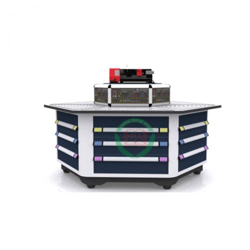
(3) Training table
The training table of the electrician electrical and motor dragging skill training device is an iron double-layer matt dense pattern sprayed plastic structure. The tabletop is fireproof, waterproof, wear-resistant high-density board, solid structure, and beautiful appearance. There are two drawers (with locks) on the left and right of the table, and a cabinet, where you can place pendants and training items.
3. Configuration List
1. Experimental table : steel-wood structure, the size is 1600 × 800 × 1600mm
2. Experimental screen : with slot, for embedding training module
3. Main console : equipped with control power supply and instrument
4. The motor drive Training Module : AC contactors, thermal relays, time relays, switches, terminals and the like mounted on the panel, with a single-phase capacitor motor 1 , three-phase squirrel-cage motor 1 stage, two-speed asynchronous motor 1 Taiwan, using panel sockets on the motor
The programmable controller ( the PLC ) training module – Optional : the PLC (optional various brands) of the IO port leads to the panel socket with 16 analog training module, comprising a simulated lift, a small stepping motor , digital control , LED simulation.
6. Frequency conversion speed regulation ( VFFF ) training module : frequency converter (various brands optional) is installed on the panel, the motor is installed on the guide rail, with rotary encoder
7. Touch screen ( HMI ) training module -optional : touch screen (optional for various brands) is installed on the panel
8. Intelligent electrical fault setting and troubleshooting assessment system -optional : intelligent man-machine dialogue platform (answerer) is composed of Chinese LCD screen, microcomputer and touch keyboard. Operation unit circuit board (integrated with display), keyboard. The operation unit can be offline for offline evaluation; it can be automatically scored: the display screen prompts when there is an alarm.
Mainly have the following operation functions:
( 1 ) Student entrance: used when the student removes the fault, you can check the remaining time of the assessment.
( 2 ) Teacher entrance: set faults, remove all faults, set assessment time, modify login password, set device number. The teacher entrance requires a login password.
( 3 ) Querying scores: Query the students’ current scores.
( 4 ) Student ID query: query the student ID set by the teacher through the computer.
( 5 ) Device number query: query the device address of the machine, each operating unit has a unique device address.
( 6 ) Start of assessment time: used for the teacher to count down after the assessment time is set.
9. PLC control object model -optional : see PLC teaching equipment
4. the types of experiments that can be completed by the electrician electrical and motor dragging skill training devices (must be equipped with corresponding training modules)
1. Motor drag training (with teaching motor)
2. General machine tool electrical control training (with teaching motor)
3. The programmable logic controller ( the PLC ) programming training (with 16 simulation training modules)
4. Frequency conversion speed regulation ( VFFF ) training
5. Touch screen ( HMI ) control training
Some experimental items of electrician electrical and motor drag skill training devices:
1. Three-phase asynchronous motor direct start control circuit
2. Three-phase asynchronous motor jog control circuit
3. Self-locking control circuit of three-phase asynchronous motor
4. Three-phase asynchronous motor button interlocking forward and reverse control circuit
5. Three-phase asynchronous motor contactor interlocking forward and reverse control circuit
6. Three-phase asynchronous motor double interlocking forward and reverse control circuit
7. Three-phase asynchronous motor worktable automatic round-trip control circuit
8. Two three-phase asynchronous motors start and stop sequentially control circuit
9. Two-phase control circuit of three-phase asynchronous motor
10. Y- △ control of contactor control
11. Y- △ control of time relay control
12. Three-phase asynchronous motor unidirectional start reverse connection brake control circuit
13. Three-phase asynchronous motor without transformer half-wave rectification one-way starting energy consumption braking control circuit
14. Three-phase asynchronous motor has transformer full-wave rectification and unidirectional starting energy consumption braking control circuit
15. Three-phase asynchronous motor forward and reverse start energy consumption braking control circuit
16. Single-phase squirrel-cage motor capacitor start control circuit
17. Two-speed AC asynchronous motor manual variable speed control circuit
18. Two-speed AC asynchronous motor automatic variable speed control circuit
19. Y- △ start control circuit for power-off delay DC energy consumption braking
20. Y- △ start control circuit with DC power consumption delay during power-on delay
21. Three-phase asynchronous motor double interlocking forward and reverse energy consumption braking control circuit
22. Three-phase asynchronous motor double interlocking forward and reverse start reverse connection brake control circuit
23. Electric control circuit of C620 lathe
24. Electric hoist electrical control
25. Y3150 hobbing machine control circuit
26. Basic instruction operation of programmable controller
27. LED digital display control
28. Simulation of Light Control of Sky Tower
29. Simulation of traffic lights at intersections
30. Simulation of the control action of the answering machine
31. Simulation of four-section conveyor belt
32. Simulation of assembly line control
33. Simulation of five-phase stepper motor control
34. Water tower water level simulation control simulation
35. Simulation of simulation control of liquid mixing device
36. Simulation of simulation control of mail sorter
37. Simulation of rolling mill simulation control
38. Simulation control of automatic molding machine
39. Simulation of automatic feeding and loading control
40. Simulation of automatic washing machine control
41. Simulation of electroplating production line control
42. PLC controlled three-phase asynchronous motor forward and reverse control
43. PLC controlled three-phase asynchronous motor Y- △ start control
44. PLC controlled three-phase asynchronous motor step-down start control
45. PLC controlled three-phase asynchronous motor energy consumption braking control
46. Inverter function parameter setting and operation
47. Inverter alarm and protection function
48. Multi-speed selection of frequency conversion speed regulation
49. External terminal jog control
50. Control motor forward and reverse motion control
51. Control the operation time of the motor
52. Parameter setting of inverter with instant power failure
53. External voltage frequency control
54. External current frequency control
55. Frequency conversion open-loop speed regulation of three-phase asynchronous motor
56. PLC controls the positive and negative motors of the external terminals of the inverter
57. PLC control motor running time control of inverter external terminal
58 . Based on PLC digital control multispeed
59 . Based on PLC converter open-loop speed communication scheme
60 . Based on PLC speed closed loop control communication
61 . Analog converter Water Supply System
62 . The basic programming instructions to practice based on the touch screen control mode
63. . Based on the touch screen control mode LED control
64. Communication control between PLC , touch screen and inverter